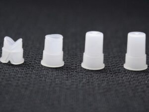
In recent years, 3C products such as notebook computers, mobile phones and personal digital assistants have been updated very quickly. The design concept of products is developing in the direction of “light, thin, short and small”, and people’s demand for these products is also growing rapidly. As a result, thin-wall injection molding technology has developed rapidly.
Thin-wall injection molding technology has attracted people’s attention, and developed countries led by the United States, Germany and Japan have invested heavily in the development and research of this technology. It has become a new research hotspot in the plastic molding industry, and it is a future technology with far-reaching significance and important functions.
Definition of Thin-Wall Injection Molding Technology
Thin-wall injection molding, also referred to as TWIM, is a technology that doesn’t have a universally accepted definition as of now.
According to scientists Mahishi and Maloney, it can be defined based on the flow length thickness ratio, L/T. This is the ratio of the flow length (L), from where the melt enters the mold to the furthest point in the cavity that needs to be filled, to the corresponding average wall thickness (T). If this ratio exceeds 100 or 150, it’s considered thin-wall injection molding.
On the other hand, Whetten and Fasset propose a different definition. According to them, if the thickness of the molded plastic part is less than 1 mm, and the projected area of the plastic part is more than 50 cm2, it falls under thin-wall injection molding. Some scholars also define thin-wall injection molding as a process where the wall thickness of the molded plastic part is less than 1 mm (or 1.5 mm), or where the ratio of the part thickness (t) to part diameter (d), for disc-shaped parts, is less than 0.05.
These varying definitions demonstrate the complexity of establishing a definition of thin-wall injection molding that can cater to all kinds of plastic raw materials and part shapes. Furthermore, as technology evolves, the critical value defining thin-wall injection molding is likely to change, reinforcing the notion that it’s a relative concept.
1. Thin-Wall Injection Molding Injection Molding Machine
Thin-wall injection molding presents a unique challenge for conventional injection molding machines. The rapid filling time required for this technique makes it impossible to adhere to the speed curve within this brief duration. To overcome this, high-resolution microprocessors are essential for controlling the injection molding machines.
During the thin-wall injection molding process, both pressure and speed must be independently managed concurrently. In conventional machines, the filling stage is controlled by speed, making the traditional method of transitioning to pressure control in the holding stage unfeasible.
Thin-wall injection molding machines typically necessitate smaller barrels compared to the larger barrels of traditional machines. Given the reduced wall thickness of the plastic parts, less material is required for each injection.
Using an oversized barrel can lead to plastic raw materials cracking from extended residence times. As such, the optimal injection volume for machine selection should be between 35% and 75% of the machine’s maximum injection volume. To adapt to these demands, it’s crucial for machinery and equipment manufacturers to collaborate with research institutions in developing specialized injection molding equipment.
2. Design Technology of Thin-Wall Injection Molding Mold
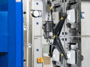
Mold design is a crucial part of thin-walled injection molding, and special molds are generally required for thin-walled products. Compared with the standardized mold of conventional products, the mold of thin-walled products may have major changes in mold structure, pouring system, cooling system, exhaust system and demoulding system. It is mainly manifested in the following aspects:
- Enhanced Strength: The mold structure is to withstand the high pressure during molding. The rigidity and strength of the thin-walled injection molding mold must be high. The mold may have more internal locking positioning mechanisms to ensure accurate positioning and good side support. Bend and offset.
Therefore, the thickness of the movable and fixed templates and their supporting plates of the mold is usually thicker than that of the conventional mold, and there are more support columns.
- Optimizing Gating Systems: The gating system is crucial for forming thin-walled plastic parts. When dealing with minuscule plastic part thickness, it is recommended to utilize a large gate that is wider than the wall thickness. For straight sprue applications, the addition of a cold slug well can help alleviate gate stress, facilitate filling, and minimize damage during the plastic part’s removal from the gate.
To ensure that thin cavities are filled effectively, the pressure drop in the runner system should be as low as possible. Ideally, the pressure drop of the runner should not exceed 15% of the pressure provided by the injection molding machine. The cross-section design of the runner is larger than traditional designs, and the melt’s residence time must be limited to prevent plastic degradation and cracking.
Certain molds for thin-walled plastic parts incorporate hot runner technology and sequential valve gate (SVG) technology into their gating system. Hot runner technology enables the melt to offer the highest possible pressure at the gate after traversing a long flow path. Hot runners can also cause the melt to remain at high temperatures for extended periods, potentially degrading and cracking the plastic.
Therefore, controlling the residence time is crucial. SVG technology, a new stage control hot runner technology developed by GE Company in the United States, has been instrumental in molding thin-walled plastic parts. It significantly reduces the flow length of larger plastic parts and has been vital in producing larger thin-walled plastic parts like laptop casings.
- Strengthening cooling measures: The thin-walled plastic parts of the cooling system cannot withstand large residual stresses caused by uneven heat transfer like conventional plastic parts. In order to ensure the dimensional stability of the plastic parts and control the shrinkage and warpage within an acceptable range. It is necessary to strengthen the cooling of the mold to ensure a balanced cooling.
- Exhaust system: Thin-wall injection molding molds generally need to have good exhaust performance, and it is best to perform vacuuming operations. Due to the short filling time and high injection speed, it is very important to fully vent the mold, especially in the accumulation area of the flow front, to prevent the ignition of trapped gas.
- Demolding system: Because the walls and ribs of thin-walled plastic parts are very thin, they are very easy to damage, and the shrinkage along the thickness direction is small. The high holding pressure makes the shrinkage smaller, making the ribs and other small structures easy to stick combine. Thin-wall injection molding should use more and larger ejector pins than conventional injection molding to avoid knock-through and sticking.
This table highlights key considerations for the demolding system in thin-wall injection molding, focusing on the challenges posed by the delicate nature of thin-walled plastic parts and the measures to prevent damage and sticking during the demolding process. The additional column provides recommended approaches to address each consideration effectively.
| Consideration |
Importance |
Recommended Approach |
| Wall and Rib Thickness |
Very thin walls and ribs increase susceptibility to damage during demolding. |
Optimize cooling system to control cooling rate and reduce warpage. |
| Shrinkage Control |
High holding pressure to reduce shrinkage along the thickness direction. |
Use precise pressure and temperature control to minimize shrinkage. |
| Avoiding Rib Sticking |
Use more and larger ejector pins to prevent knock-through and sticking of ribs and small structures. |
Implement proper venting and lubrication to facilitate easy ejection. |
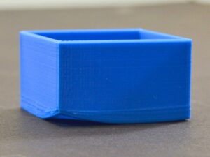
3. Design Technology of Thin-Wall Injection Molding Products
The design principles of thin-walled products are also very different from those of conventional thick-walled products, and are also affected by molding limitations and the choice of plastic raw materials. Thin-walled products require high impact strength, good appearance quality, dimensional stability, and precise dimensional tolerances, and can withstand large static loads.
During the design process, the rigidity, impact resistance and manufacturability of the product should be considered.
4. Selection of Plastic Raw Materials for Thin-Wall Injection Molding
The plastic raw materials used in thin-wall injection molding have better fluidity, and need to have large flow length, high impact strength, high heat distortion temperature, high thermal stability, low directionality and good dimensional stability. In addition, low-temperature impact rigidity, flame retardancy, mechanical assembly and appearance quality of plastic raw materials should also be considered.
At present, the plastic raw materials widely used in thin-wall injection molding include polycarbonate (PC), acrylonitrile-butadiene-styrene (ABS), PC/ABS blends and PA6. This may be due to the need to use plastics with better physical properties to maintain product strength as the wall thickness decreases.
5. Main Problems in Thin-Wall Injection Molding
Although thin-walled plastic parts have many advantages, it reduces the formability of plastic parts, so that these thin-walled plastic parts cannot be molded by conventional injection molding methods. When molding thin-walled plastic parts, there are three common problems: short shots, warping and weld lines.
1. Short Shots
Refers to the incomplete quality defects of plastic parts caused by incomplete filling of the mold cavity, the melt has condensed before the filling is completed. If a plastic part is incompletely filled, it can be judged as a substandard product without considering other quality defects. The filling process and cooling process of conventional injection molding are intertwined.
When the polymer melt flows, the melt front encounters the core surface or the cavity wall with a relatively low temperature, and a condensation layer is formed on the surface. The melt continues to flow forward in the condensation layer. As the thickness of the condensation layer increases, the actual cavity flow path becomes narrower. The thickness of the condensation layer has a significant impact on the flow of the polymer.
The thickness of the plastic part is relatively thick during conventional injection molding. The influence of the condensation layer on the injection molding is not very great at this time.
However, in thin-wall injection molding, when the ratio of the thickness of the condensation layer to the thickness of the plastic part gradually increases as the thickness of the plastic part becomes thinner, this effect is great. Especially when the size of the two can be compared with each other is more prominent.
Research has underscored that the influence of the condensation layer on flow multiplies exponentially as the thickness of the plastic part diminishes. This underlines the critical role that the condensation layer plays in thin-wall injection molding.
When considering injection molding, it becomes essential to equip the injection molding machine with a high injection rate. This ensures the pace at which the plastic melt fills the cavity outstrips the condensation layer’s growth rate, thereby enabling the completion of the filling action prior to sealing. This is a crucial prerequisite for thin-walled plastic parts’ injection molding.
Fasset pointed out that when the flow length is 300 mm and the wall thickness of the plastic part is 3.0 mm, the L/T is 100 at this time, which can be easily achieved by conventional injection molding technology. However, when the wall thickness of the plastic part drops to 1.0 mm Below that, the flow length-to-thickness ratio (100), which was once easy to achieve, becomes very difficult to achieve.
2. Warpage
Warpage is a defect in plastic parts caused by uneven internal stress. The causes of warpage are uneven shrinkage, uneven orientation and uneven cooling. When the warpage deformation value exceeds a certain value, the plastic part will be regarded as unqualified, and the thin-walled plastic part has a great influence on the warpage.
The requirements are more stringent. The warping and deformation defects of plastic parts can be improved by balancing the cooling system, adjusting cooling time, holding pressure and holding time.
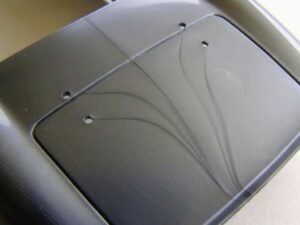
3. Weld Line
The boundary formed when two or more melt flow fronts in the cavity are fused. The weld line not only affects the appearance quality of the plastic part, but also tends to generate stress concentration at the weld line. It weakens the mechanical strength of the plastic part, which is particularly unfavorable to the mechanical properties of the plastic part, especially the thin-walled plastic part.
Cracks may even form along the weld line, posing further challenges to the part’s functionality and durability. In the design, the number of gates can be reduced or the position of the gate can be reduced or the position of the weld line can be changed to meet the design requirements of the plastic part.
Dive Deeper Into Our Resources
Looking for more diverse service options? Browse through our handpicked selections:
For some insightful reads, we’ve curated a list of recommended articles just for you:
Still haven’t found what you’re looking for? Don’t hesitate to contact us. We’re available around the clock to assist you.